
While instrument landing systems (ILS) see far less use today with the increasing development of RNAV (GPS) approaches, ILS approaches are still common and form the backbone of precision approaches available today. With the bonus of possible added precision beyond what GPS can provide and immunity from GPS interference, these approaches will remain a staple for years to come. In this world of GPS as king, we should remain proficient in ILS use and be careful to avoid their few gotchas.
Fundamentals
A complete ILS installation consists of the localizer and the glideslope, each being related but separate systems. The localizer transmitter and antenna array were developed in the late 1930s which was quickly followed by the glideslope transmitter and its antenna array. Both the LOC and GS are ground-based navigation aids as opposed to satellite-based aids. (See sidebar for GNSS glidepath guidance). The ILS uses a radio signal whose beam is formed by an antenna array.
The LOC transmits on VHF frequencies of 108.10 to 111.95 MHz in channels 0.05 MHz apart. The glideslope is paired with the LOC frequencies and transmits in the UHF range of 329.15 to 335.00 Mhz. The pairing of the LOC and GS means you don’t have to set the glideslope frequency into another receiver. By selecting the LOC frequency, the GS frequency is automatically selected for you. However, the Morse code identifier (You do listen for the identifier, don’t you?) only indicates the status of the LOC transmitter, not the Glideslope.
The localizer transmitter/antenna array is positioned at the far end of the runway, and the glideslope transmitter/antenna array is set to either side of the runway approximately a thousand feet from the approach end. While the ILS concept was developed over 80 years ago, the utilization of sideband transmissions, phased antenna arrays, depth of modulation measurements and space modulation are what still make the LOC and GS “modern marvels.”
Both the LOC and GS use modulation tones of 90 Hz and 150 Hz. For the glideslope, a predominant 90 Hz tone generates a fly-down command, and a 150 Hz tone generates a fly-up command. When both tones are of equal amplitude (the depth of modulation is the same), you are on the glideslope. The amount of command is proportional to the amplitude of the 90 Hz and 150 Hz tones.
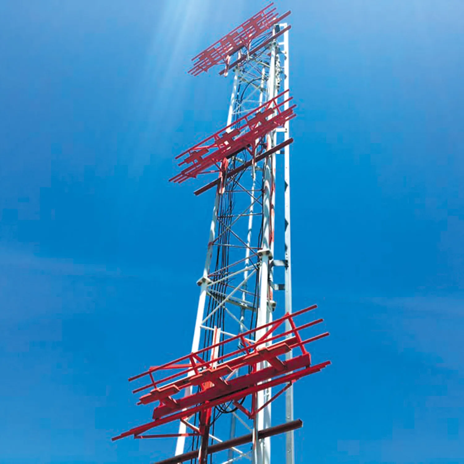
The antenna patterns are not single lobes of 90 and 150 Hz as depicted on many drawings. There are three lobes, a center lobe and overlapping lobes above and below the center. The GS antenna tower photograph above shows the three corner reflector antennas, whereas the simplest systems only use two antennas to generate the three lobes (CSB and two SBO lobes).
Unlike the LOC, there are many types of GS implementations. The glideslope antenna pattern is more complicated due to the small (approximately three-degree) inclination angle. Because of this small inclination angle, the lower lobe will have a significant portion of its energy hitting the ground. Many glideslope installations turn this problem into a feature, reflecting the lower lobe off the ground ahead of the antenna.
Glideslopes that utilize reflected energy are called Image type and they are further differentiated into Null Reference, Sideband Reference, and Capture effect. There are also Suppressed Image Glideslopes that don’t utilize ground reflections. However, they all have superfluous lobes that contain the same 90 and 150 Hz modulation tones.
These lobes are above the three-degree glideslope at odd multiples of three degrees (nine degrees, 15 degrees, etc.). However, the transition between the desired and false glideslope can get interesting. Complicating the issue even further, depending on what type of antenna has been installed—which you have no way of knowing—the false glide slope can have a “repeated signal” or an “inverted signal.”
The glideslope receiver reacts oddly to a repeated secondary glideslope signal. If you are above the primary and below the first secondary—between six and nine degrees—the secondary glideslope will provide a fly-up command (away from the primary glideslope.) If you are on an inverted secondary signal, your indication would be to fly down.
Capture From Above
The takeaway of this article is to alert you that there are false glideslopes that your autopilot could latch onto if you are not careful. The resultant elevator movements will be excessive and may be the opposite of what is required to capture the desired glideslope. While the information is somewhat dated, by 2014 NASA’s Aviation Safety Reporting System had collected 57 occurrences of false glideslope captures. The Dutch Safety Board declared false glideslope captures a significant threat to aviation safety.
The number of occurrences is expected to increase as more general aviation cockpits are outfitted with digital autopilots and are flown by less experienced pilots. You can intercept a false glideslope when hand-flying the ILS, but it is unlikely that you will generate excessive elevator movements to try to track the false signal. The autopilot will happily follow the false signal.
Today’s digital autopilots offer all the modes used in airline cockpits. Being able to arm the approach is one of the best features. Airline crews have been warned about arming for the approach too soon, especially if they are high. The “window” for a LOC capture is broader than that for the glideslope and most systems have logic that the LOC must be captured first before the GS.
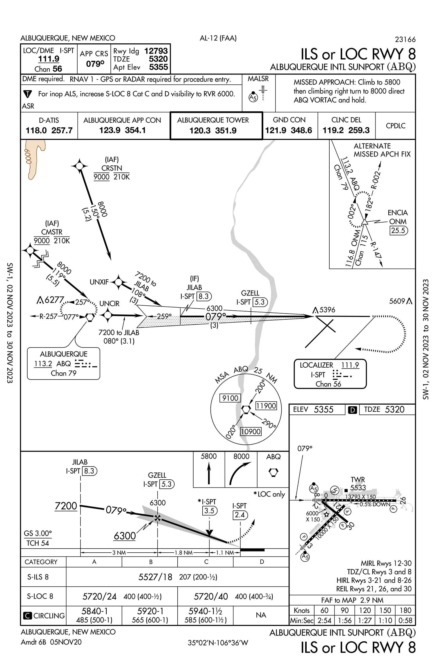 Look at the Albuquerque ILS RWY 8. If you are arriving from the east, you’ll be high to clear the Sandia Mountains. (MSA is 11,900 feet.) You don’t have to be that high to receive the false glideslope.
If you are slow in descending and cross the final approach fix, GZELL, at 7600 feet you will be on a seven-degree descent angle to the runway which is in the false glideslope region (anything above six degrees). You will receive a fly-up indication if it is a “repeated signal” installation. In the false glideslope region, you and the autopilot will receive an incorrect command or a command with a very high descent rate. Being high on the initial approach exposes you to receiving, and possibly capturing, a false glideslope.
Another way to capture a false glideslope is if you have a digital autopilot and aren’t careful about when and where you set the altitude preselect on the approach. Say you’ve captured the localizer but not the glideslope. The descent to capture the glideslope is going great when the aircraft suddenly levels out. What happened? You may have an autopilot where altitude select is automatically armed whenever another vertical mode is active. If coupled, the autopilot will never allow the aircraft to fly through the altitude set in the altitude preselector. Perhaps you inadvertently set the altitude preselector just above the altitude where the glideslope capture would have taken place.
The aircraft levels out, and while you are trying to figure out what happened to your perfect approach, the angle to the touchdown point is increasing. If you disengage and reengage the approach mode after a few seconds of confusion, you may have already entered the false glide slope region. The French BEA Incident Investigation into the AIRBUS A318-100 Incident on 20 December 2019 provides more detail on this problem. (The full incident report is online.) Older autopilots, before the Collins FCS-65, with separate ALT and ALT SEL modes, did not have this issue.
Prevention
The pilot should check the aircraft’s position before selecting approach mode, especially when descending to intercept the glideslope. A quick rule of thumb is your altitude should be less than half the nautical-mile distance to the runway multiplied by 1000. For example, using the ABQ ILS RWY 8 approach, at the final approach fix of GZELL, you should be no higher than (1.8+1.1) ÷ 2 × 1000 = 1450 feet AGL, or 6770 feet MSL here.
You can go further out to see when it is safe to arm the APR mode. At JILAB you should be below: (3+1.8+1.1) ÷ 2 × 1000 = 2950 feet above the runway or 8270 MSL. This will ensure you can safely arm APR without worrying about capturing a false glideslope. Cross-check your calculation to ensure it doesn’t indicate an altitude lower than the altitude shown on the approach chart, then rigorously fly the charted altitudes without being significantly above them.
Additional Reading
Airbus has a safety magazine, Safety First, available online. The magazine has valuable articles on aviation safety. “Lining Up with the Correct Glide Slope” in the December 2021 issue discusses the issue of false secondary glideslopes and is quite informative.
The glideslope discussed in the article is a part of a ground-based Instrument Landing System that provides precision approach guidance. The ILS requires transmitters, antenna arrays and site preparation to ensure proper operation. The glideslope signal has to be demodulated to determine if you are above or below the glideslope.
On the other hand, a glidepath is generated internally by the Global Navigation Satellite System (GNSS) or the Flight Management System. The fact that a glidepath doesn’t require expensive ground-based transmitters or site preparation is the main reason for the explosion of approach procedures in the last 20 years. (See “Culling Procedures” in February 2022 IFR). Another advantage of a glidepath is there are no false glidepaths above the desired vertical path as there are with glideslopes.
VNAV vertical guidance has gotten so good that Localizer Performance with Vertical Guidance (LPV) approaches are so much like ILS approaches that the FAA considered eliminating ILS approaches a few years ago. (They dropped this idea when it was pointed out if the GNSS went down, there would be no precision approaches available).
A glidepath requires no information other than the altitude of the waypoints and the aircraft’s location and altitude. For an RNAV/VNAV approach, the waypoint heights are predetermined based on the procedure. VNAV descents have been around for several decades. (U.S. Patent for Vertical Navigation Control System was granted March 15, 1977.) LNAV/VNAV descents and approaches utilize barometric altitude for descent guidance. Whereas LPV approaches, using the WAAS/RAIM approved GNSS receivers, use GPS altitude rather than Baro altitude for the vertical guidance calculation.
The LPV glidepath is simply a trigonometry problem. The database has the runway touchdown point and its elevation plus it has the glidepath angle, usually three degrees. The system knows from on-board sensors the aircraft’s position and altitude. The trig problem is knowing the two sides (horizontal distance and height above the touchdown point, calculating the present angle compared to the desired angle). The glidepath needle will indicate the deviation and the autopilot will be fed a GS-like signal to track the glidepath. If it is a VNAV (Baro altitude) approach the annunciation is the same (APR) but the flight director will usually feed the autopilot a vertical speed target that will change to keep the aircraft on the desired glidepath.
David Rogers from Honeywell has an interesting article “Understanding Glidepath Differences,” which can be found online. The article has an excellent discussion of LPV approaches.
—BT


