For “land” aircraft, all flights start and end at an airport or airstrip, and an important aspect in planning an IFR flight to an unfamiliar airport is to study not only the approach and departure charts, but also the airport diagram to fully understand the big picture. Typically, we think of airport diagrams as useful and important tools like “taxi diagrams,” but they are much more than that. In this Chart Clinic, we will start by dissecting the Airport Diagram for Reading Regional Airport / Carl A Spaatz Field (KRDG) before considering two of its approach charts.
Land and Hold Short
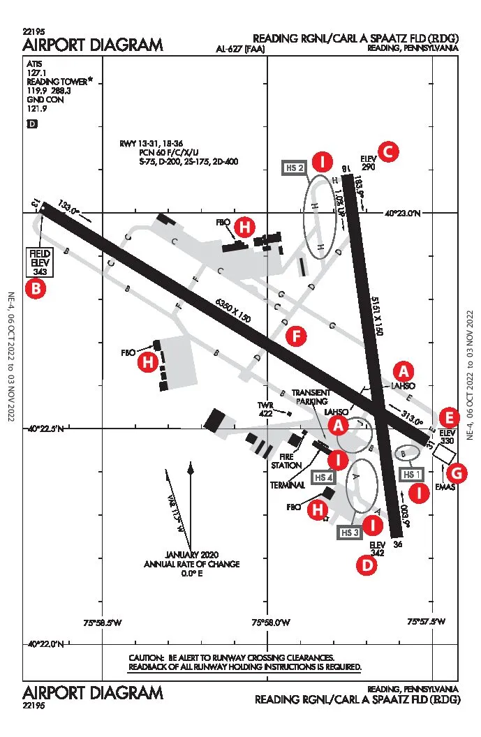
Reading uses LAHSO (Land and Hold Short Operations) [A] when both Runway 13 and Runway 18 are in simultaneous use. When this occurs, one of the two runways (or both) needs to resort to LAHSO operations. If the tower instructs an aircraft landing on Runway 13 to land and hold short of Runway 18/36, the pilot needs to agree; or otherwise respond: “unable.” The LAHSO location is painted on the runways using the same pavement markings used in the hold short line between a taxiway and a runway; two solid lines, then two dashed lines.
If the “Hold Short” is accepted, the aircraft must come to a complete stop before the Hold Short markings and wait for tower instructions. ATC mentioned to me two possibilities for Runway 13; one is to back taxi on Runway 13 to Taxiway Delta or proceed forward and exit on Juliet. A third and more likely scenario is proceeding across the intersecting runway when the conflicting traffic is clear.
An unsuspecting pilot, during a non-LAHSO landing, may see the two solid lines of the hold short line marking straight ahead and interpret that the airplane needs to stop before the line and stomp on the brakes. Perhaps different markings to indicate the LAHSO position would be less confusing, but for now the marks are the standard hold short marks.
Field Elevation vs. TDZE
The Touch Down Zone (TDZ) is the first 3000 feet of the runway, and the elevation of the TDZ is called Touch Down Zone Elevation (TDZE). The field (airport) elevation [B] is the elevation of the highest TDZE. At Reading, the highest TDZE is 343 feet (or 344 feet, depending on the reference) of RWY 13. The other three runways have lower elevations: 290 feet MSL RWY 18 [C] , 342 feet MSL RWY 36 [D] and 330 feet MSL RWY 31[E] .
On straight-in approaches, the Decision Height (DH) or Minimum Descent Height (MDH) above TDZ is the HAT (Height Above Touchdown). But what about circling approaches since any runway is usually acceptable for a circle-to-land?
The Height Above Airport (HAA) is used instead, and it is the height between the MDH and the Airport Reference Point (ARP). But where is the ARP at Reading? Unfortunately, government charts don’t indicate the location of the ARP on Airport Diagrams, but Jeppesen charts do. [F] The ARP is located east of taxiway Delta, just south of Charlie.
The ARP is also the latitude/longitude position of the airport. In a GPS navigator, KRDG as a waypoint uses the ARP as the location. GPS distances in nautical miles are then to the ARP. Typically, when the tower says, “report X miles out,” that usually means a distance from the landing runway. Keep in mind when using GPS to measure the distance to the runway, the displayed GPS distance will be off by the distance from the ARP to the runway. Usually, at smaller airports, the difference is insignificant, but at larger airports, the difference could easily be two or more miles.
Checking Altimeter Accuracy
According to AIM 7-2-3, if the difference in indicated altitude between a known field elevation and the altimeter “… is in the order of plus or minus 75 feet, the accuracy of the altimeter is questionable.” With Reading as an example, what reference is used as a known elevation to test the altimeter’s accuracy while on the ground? The only known field elevations are at the runway thresholds, and the difference between the highest and lowest published elevations at Reading is 53 feet, a large percentage of the tolerance of plus or minus 75 feet.
One item not listed in any pre-takeoff checklist that I have seen is: Verify Altimeter Accuracy. Perhaps occasionally, when taxiing into position on the runway for take-off, we should quickly verify that the indicated altitude is within 75 feet of the TDZE. However, don’t reset the altimeter to match the TDZE. If it is outside of the tolerance limit, it’s time to take the altimeter to an instrument shop.
EMAS
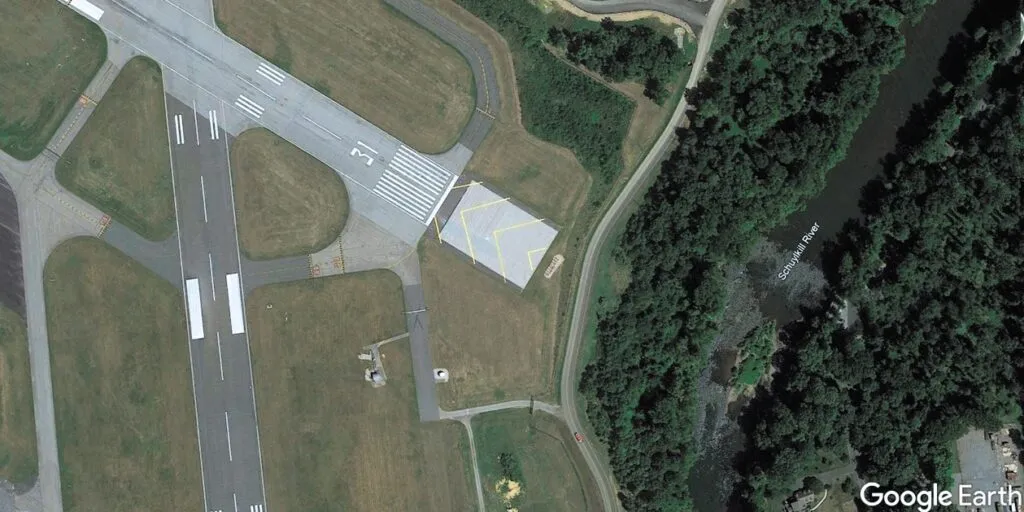
At the end of RWY 13, there is a rectangle annotated EMAS,[G]. Engineered Materials Arresting System, also known as the arrester bed, consists of “high energy absorbing materials of selected strength, which will reliably and predictably crush under the weight of an aircraft. Its purpose is to stop an aircraft overrun with no human injury and minimal aircraft damage when there is an insufficient free space for a standard runway safety area (RSA).” (AC 150/5220-22B)
The presence of an EMAS at Reading indicates an aircraft may need assistance in stopping if a long landing or aborted takeoff results in its going beyond the end of Runway 13. In the case of Reading, the question is why? And why only at the end of Runway 13? The answer is found on Google Earth. Beyond the end of Runway 13 are a road, trees, and the Schuylkill River. Better to be stopped on the EMAS bed than end up wet in the river. But don’t taxi onto the EMAS by error, as it could result in an expensive EMAS repair.
FBO Locations
Another advantage of reviewing the airport diagram is to identify FBO locations. [H] There are three; landing on Runway 13, knowing the location of the selected FBO would indicate if you should turn left or right onto a taxiway. Of course, if a pilot turns off the runway in the wrong direction, ground control will redirect as appropriate.
Hot Spots
The FAA defines a hot spot as “a location on an airport movement area with a history or potential risk of collision or runway incursion, and where heightened attention by pilots and drivers is necessary.” Reading has four, [I] with three located near each other. While hot spots are charted on airport diagrams, there is no signage on the taxiways. At night, even more, vigilance is needed.
Decision Heights, Visibilities
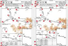
The decision height (DH) for the ILS RWY 13 approach is 200 feet AGL with a ¾ SM visibility (Category A aircraft) [J] compared to a DH of 582 feet AGL for the RNAV (GPS) RWY 13 approach with a 2 SM visibility (all aircraft Categories). [K] The difference of 382 feet in DH is considerable between the two approaches. Both have similar final approach segments, even using the same waypoints.
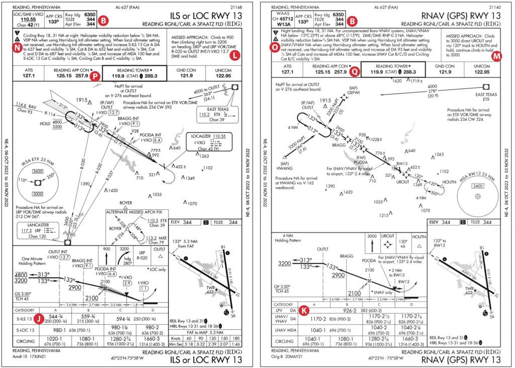
The variation in DHs is explained by the missed approach segment. On the ILS, the missed approach requires a climb of 356 feet to 900 feet MSL [L] from the DA of 544 feet MSL, followed by a climbing right turn. On the GPS approach, the missed approach requires a straight-ahead climb direct to UROUT, followed by a left seven-degree change in direction, climbing to 3000 feet MSL. [M] The reason for the higher DH is a ridge line that is perpendicular to the missed approach course and the highest point of the ridge, 1349 feet MSL, right below the track of the missed.
Had the missed for the GPS approach followed a similar course as the missed for the ILS approach, most likely, the DH for the GPS would have been lower. Another option could have required a higher climb gradient rather than the standard 200 feet/NM gradient, which is assumed for the GPS missed.
Night Limitations
This is an example of approaches designed on different dates using different wording. The “older” ILS RWY 13 approach states, “Circling Rwy 18/31 NA at night.” While circling at night is not permitted, nothing is said about landing at night. [N] However, in the newer chart for the GPS approach RWY 13, it indicates “Night landing: RWY 18, 31 NA.” [O] Besides not landing at night, that would also imply no circling to land at night on those runways. The GPS RWY 18 approach chart (not shown) states the same thing as the GPS RWY 13 approach: “Night landing: RWY 18, 31 NA,” implying no circling to RWY 31 and no straight-in landing to RWY 18. (RWY 31 has no approaches.)
I clarified with ATC what is and is not allowed regarding night landings. Pilots can land on all four runways at night but cannot land at night from an instrument approach to RWY 18 or circle-to-land to RWY 18 and RWY 31 at night. But if you are doing a visual approach (which is not an instrument approach) under IFR to RWY 18 and 31, a pilot can land at night. Go figure!
Part-Time Approach Control
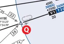
Reading Approach is part-time [P Q] so pilots have to look in the chart supplement for the backup. Harrisburg Approach takes over when Reading Approach shuts down. Jeppesen publishes directly on the approach chart to contact Harrisburg on 124.1 MHz when “Reading Approach is INOP.” Unlike the government airport diagram, Jeppesen additionally publishes the Departure (Reading and Harrisburg) and Unicom frequencies.
Luca F Bencini-Tibo was very surprised several years ago when overnight, the Fort Lauderdale International Airport (KFLL) suddenly gained 55 feet of elevation from 10 feet to 65 feet. A new runway opened and one end of the runway sloped upward to allow cars to pass underneath the runway through a tunnel.
That EMAS just before Runway 31 is there to keep Runway 13 overruns out of the river.
