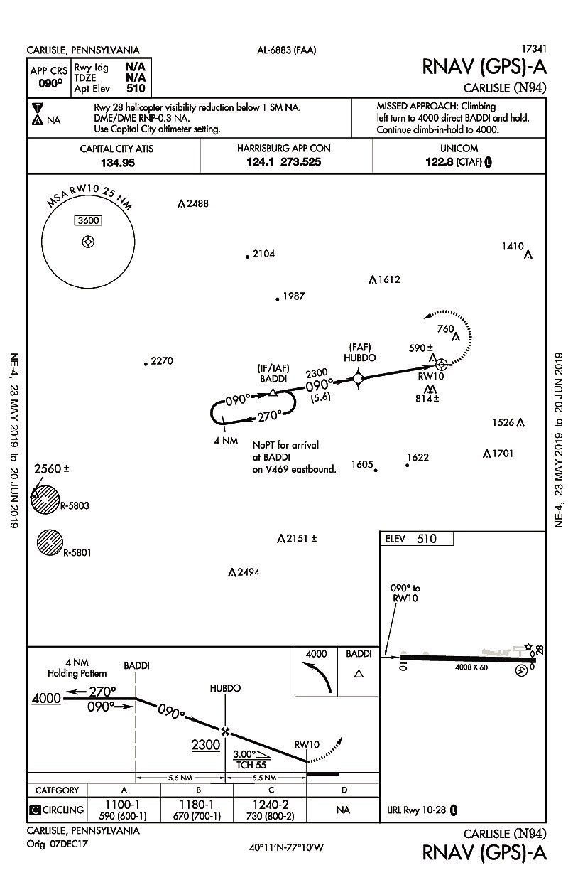
Recently, we heard from a reader with a question about an approach into Carlisle, Pennsylvania (N94). The RNAV (GPS)-A approach has a final approach course that’s offset from the runway by around 12 degrees and a standard three-degree descent angle. Approaches are usually published with only circling minimums when the final approach course alignment relative to the runway exceeds 30 degrees (for most procedure types) or the descent angle is greater than 3.77 degrees (for Category C and below). Since neither of these reasons apply to this approach, why doesn’t it have straight-in minimums?
It turns out that the reason this procedure has only circling minimums has to do with the runway markings, of all things. The runway at Carlisle has basic, visual, runway markings; airport design standards call for at least non-precision instrument markings in order to publish straight-in minimums. This little detail isn’t found on the chart, the Airport/Facility Directory, or most EFBs, but can be found in online sources, such as Airnav.com, which include FAA airport survey data. If not for the visual runway markings, lower minimums might be possible since LP, LNAV/VNAV or LPV lines of minimums could be considered.
Approach charts have a lot of information packed onto them with every last detail included for a reason. Pilots can get an insight into the procedure, the airport, and the surrounding airspace through both what is included on the chart and what is missing. Let’s dig a little deeper into limitations that are often found on approach charts to see what insights they can reveal.
What’s In a Name?
Approach procedures are named according to the type of navigation system used to provide lateral guidance in the final approach segment (such as VOR, NDB, ILS, LOC, or RNAV). Until a few years ago, approaches often had DME included in the name if DME was required in the final segment (likewise for NDB, but those are less common), and ILS approaches with a localizer line of minimums were published as “ILS or LOC” approaches. Although these naming systems have been retired, keep in mind that there are plenty of older procedures out there that still use them and will likely stick around for a while.
This naming change comes from an effort to clarify equipment-required notes on charts. Historically, equipment (like DME) in the name indicated equipment required in the final segment, equipment required to join the approach from the en-route environment was noted in the plan view, and equipment required to execute the approach was listed on the briefing strip notes. This could make it difficult to get a complete picture of exactly what’s needed to fly the approach, but all the limitations are slowly being consolidated into a separate box above the briefing strip notes.
Like at Carlisle, approaches with only circling minimums do not have a runway included in their name (even when aligned with a runway) and instead have a suffix starting at the beginning of the alphabet included in the name. To avoid confusion, this suffix is unique for the city/state and won’t be used for other circling-only approaches regardless of the type of navigation for airports in the same city/state. For example, if there is an RNAV (GPS)-A at an airport in a given city/state, there won’t also be a VOR-A, but there could be a VOR-B. These names are often retained even if the approach with the earlier alphabetical suffix is canceled.
Alphabetical suffixes are also attached to approach names when there are multiple approaches published of the same navigation type to the same runway end (for example, RNAV (GPS) Z RWY 12). However, these approaches have both a runway indicated and an alphabetical suffix starting with Z and working backward alphabetically. These should not be confused with circling-only approaches that have a suffix starting at the beginning of the alphabet and have no runway end indicated.
Suffixes are commonly attached to straight-in approaches when there are GPS and RNP approaches to the same runway end (since RNAV is the navigation type). Other times suffixes are attached when one approach requires non-standard performance or equipment to attain lower minimums. Fun trivia: at one time these approaches were named with a numeric suffix instead of an alphabetical suffix (such as VOR/DME-1 RWY 12). There are still a couple of these found within the U.S., and this naming system is still often used outside the U.S.
Safety Below DA/MDA
Several common approach limitations exist due to penetrations of the approach visual area by obstacles. The visual area consists of two TERPS surfaces stacked on top of each other. One surface has a 34:1 slope, which is equivalent to the aircraft descent angle on a standard three-degree glidepath. The other surface has a 20:1 slope, which is significantly steeper than a normal aircraft descent angle. Since these are obstacle identification surfaces, rather than obstacle clearance surfaces, penetrations by obstructions are permitted, but result in penalties to the procedure.
Not surprisingly, pilots are expected to avoid obstacles in the visual area following an instrument approach, possibly while contending with crummy weather and poor visibility. Knowing that some of those obstacles may be uncomfortably close would be nice to know, but unfortunately the FAA doesn’t give us a direct indication about the status of visual area penetrations. However, there are limitations and symbology that allow pilots to infer the status of the visual areas.
The closest thing to a direct indication of a clear 34:1 visual area is only shown on RNAV approaches and is indicated by the presence of a light grey line (called a stipple; see the magazine cover) connecting the VDP to the runway in the profile view. Jeppesen charts note this textually as “34:1 is not clear.” Another more obscure indication of visual area penetrations is the presence of helicopter visibility reduction not authorized notes (such as on the Carlisle approach). When the 20:1 surface has penetrations, visibility reductions below one SM will be NA, and when the 34:1 surface has penetrations, visibility reductions below SM will be NA.
Another common approach limitation that can result from penetrations of the visual area is the approach being not authorized at night. Approaches at night require runway lights, so if a runway isn’t lit (possibly by NOTAM), it will be noted as NA at night. Assuming a runway has operable lights, if its 20:1 visual surface has unlit penetrations, that runway will be noted as NA at night for specific minimums, or night landing NA if it applies to all minimums.
This is why night restrictions are so important: you really don’t want to descend below MDA at night knowing there’s an obstacle that you can’t see somewhere along your path. If the runway has a VGSI it can be used to avoid the unlit visual penetration for night landings, in which case the VGSI has to be operable and the chart note requires that pilots remain at or above the VGSI glidepath until the threshold.
The presence or lack of a visual descent point (VDP) published on straight-in non-vertically guided approaches (circling approaches don’t have them at all) also allows you to gain some insight. Most notably, a VDP will not be published when the 20:1 visual area has obstacle penetrations. However, just because a VDP is not published, it doesn’t necessarily mean that there are visual area penetrations. A VDP will also not be published if the primary altimeter setting comes from a remote source, if it is inside of the MAP, or if it is outside of a stepdown fix. On non-RNAV procedures, the VDP must also be identified by a DME fix using the same DME source as other fixes in the final segment.
Additionally, sometimes VDPs that are published are not always applicable to the procedure being flown when specified conditions exist. For instance, on procedures with a secondary altimeter source, there will be a chart note telling us that the “VDP NA when using Big City altimeter setting.” This is because remote altimeters generally require an addition to the MDA, meaning the published VDP no longer applies since it was computed using the unadjusted MDA used with the primary altimeter source.
Another thing to look for is the presence of lack of a published vertical descent angle (VDA). It’s also not usually shown on circling-only approaches, but pay attention if it’s replaced with a note indicating “Descent Angle NA” (older) or “Visual Segment – Obstacles” (current). This is done when flight inspection determines a pilot descending on the vertical descent angle (VDA) would need to destabilize the aircraft to avoid an obstacle (this is bad). Removing the vertical angle is an attempt to ensure pilots don’t simply continue flying the vertical angle below MDA in these situations.
Math for Minimums
Say you’re arriving at your destination with an approach close to minimums ahead and the ATIS says the approach lights are inoperative. Will that impact your ability to legally complete the approach?
We might recognize the term “inoperative table” from training, but might not know how to apply it or even where to find it. For starters, the inoperative table describes visibility adjustments when certain lighting components are inoperative. It’s included in the front of printed terminal procedure publications (along with the chart legends, climb/descent tables, etc.). However, in the age of widespread EFB adoption, that’s not saying much. If you want to reference it as an EFB user, you typically will need to download it as a separate document named something like “Digital Terminal Procedures Supplemental.”
Approach minimums are based on full operation of all airport/runway components and visual aids associated with the approach. If something isn’t working (like lighting components, or the altimeter source), minimums likely change. It’s up to the PIC to understand the limitations and determine if the approach is affected.
As a rule, the inoperative table applies to all approaches. However, if the runway being used has no component that is included on the inoperative table, there will be a note indicating that the inoperative table doesn’t apply. In other cases, if a TERPS visibility credit for a lighting system was not included in the published minimums, the table will also not apply to that system. There are several other scenarios that could result in changes to the standard inoperative component visibility additives as well.
The lesson here is to always pay attention to any inoperative equipment NOTAMs and understand any impact on the published minimums. Also, whenever minimums need adjustment, sometimes you add to them and other times it’s a new value.
Trust the Chart
Preparing for an approach and conducting a thorough briefing for yourself (or crew) typically gives you plenty of work to do. We are certainly not suggesting adding to that workload a prescriptive list of additional things to look out for. Instead, we encourage pilots to always review chart notes and limitations on approach charts and tune their eyes to notice when certain features are missing. It’s a bonus if you know the “why” behind them, but the most important thing is to notice and abide by them.
Keep in mind that it’s not ATC’s job to police adherence to limitations; that rests squarely on the shoulders of the PIC. For example, we know of instances where ATC cleared aircraft for approaches at night, contrary to “NA at night” notes, and were confused when the pilot declined the clearance.
Remember that it’s your life and certificate on the line so when in doubt, just ask. It can also be tempting to assume that when something is missing or out of the ordinary that it is an error on the approach chart, rather than intentional. While errors do happen, they are few and far between, so chances are high that whatever you’re looking at is intentional. At a minimum, it should be given the benefit of the doubt since you likely don’t want to figure out the hard way why it’s there.


Contrary to what the article states, a 34:1 slope is not the standard 3-degree glide path. The 20:1 slope is approximately a 3-degree glide path.
Possible minor assumption by the author.. Either way, “Instrument Procedures Handbook”, figure 4-21, explains the significance of “obstacles penetrating” both 20:1 and 34:1 plains.. Whether they’re lit or not..
Good article..!