Westfield-Barnes Regional Airport (KBAF) is located on grounds that date back as far as 1905, when it was a summer training facility for the Massachusetts Army National Guard in western Massachusetts. Aviation arrived at Westfield in July 1914 when a pilot flew a Wright biplane over the town of Westfield, and the pilot was hired to drop leaflets to claim prizes from local merchants.
In 1923, the citizens of Westfield and nearby Holyoke convinced Vincent E. Barnes, the owner of the land, to sell the land to the City of Westfield for an airport. Instead, Barnes donated the land, and over the next 10 years, additional land was donated and leased by the Barnes family, amounting to about 350 acres. In 1923, it was officially named Westfield Aviation Field.
Passenger service started on October 28, 1937, flying tri-motor Stinsons to Newark, New Jersey. American Airlines flew DC-3s from 1938 to 1950, as did Mohawk Airlines from 1953 to 1959. Today, Westfield is a joint base / civilian airport where F-15 Eagles of the Massachusetts Air National Guard 104th Fighter Wing are based. The plan is to replace the F-15s in 2024 with F-35A Lightning IIs.
Westfield has five approaches to RWY 20: HI-ILS or LOC, ILS or LOC, HI-TACAN, and RNAV(GPS), and a VOR. We’ll focus on the ILS approaches. To simplify the discussion, I will refer to the first as the “military approach” and the second as the “civilian approach.”
HI-ILS or LOC RWY 20
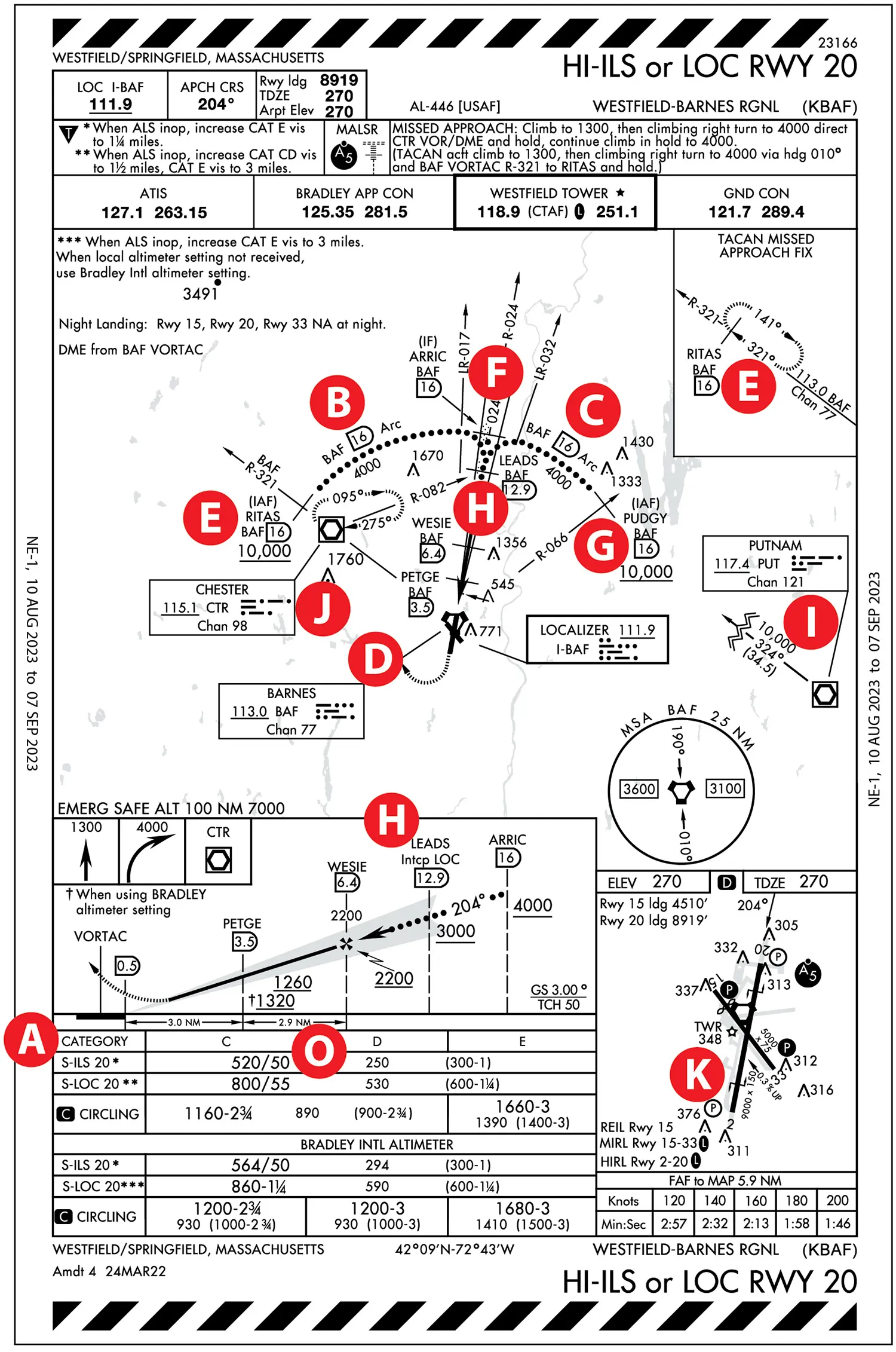 What is apparent is that the approach only applies to Category C, D, and E aircraft, excluding Category A and B aircraft. A As a review, the respective approach speeds are Category C: 121-140 knots, Cat D: 141-165 knots, and Cat E greater than 166 knots.
The approach has two DME arcs that are part of the procedure B C based on the Barnes (BAF) VORTAC for azimuth and distance information. D The clockwise (CW) arc B starts at the RITAS IAF E and ends at ARRIC intermediate fix , using the BAF R-017 as lead-in radial for turn anticipation guidance.
The counterclockwise (CCW) arc C starts at the PUDGY IAF G and also ends at ARRIC. F It uses the BAF R-032 lead-in radial. The navigation source must be changed from BAF to the LOC (I-BAF) before LEADS when the LOC is intercepted. H
Both arc IAFs start at 10,000 feet MSL or higher and end at ARRIC at or above 4000 feet MSL. Let’s do some calculations. For the CW arc, assuming a minimum ground speed (instead of an indicated airspeed) of 166 KTS for Cat E, the rate of descent is about 1065 feet per minute (FPM) from the IAF to the lead-in radial at 4000 feet. For the CCW arc, with similar assumptions but given the shorter distance, the rate of descent is more sporting—about 1750 FPM. Of course, if the approach is started at higher altitudes or flown at faster ground speeds, the required descent rates will be even greater.
PUDGY G has a feeder route from the PUTMAN VORDME (PUT) I , but because PUT is outside of the plan view, optically, it appears that it is not a direct course to PUDGY.
TACAN is not required for the approach, but if the aircraft has TACAN capabilities, there are two options for the missed approach. One ends at a hold at CHESTER VORDME (CTR). J The other missed approach uses the BAF TACAN and ends at a hold at RITAS . E
The symbol K indicates a bi-directional arresting gear in the small airport sketch on the approach chart and the airport diagram (not shown). According to the Chart Supplement legend: “Specific gear systems . . . shown on airport diagrams not applicable to Civil Pilots. Military Pilots refer to appropriate DOD publications.”
ILS or LOC RWY 20
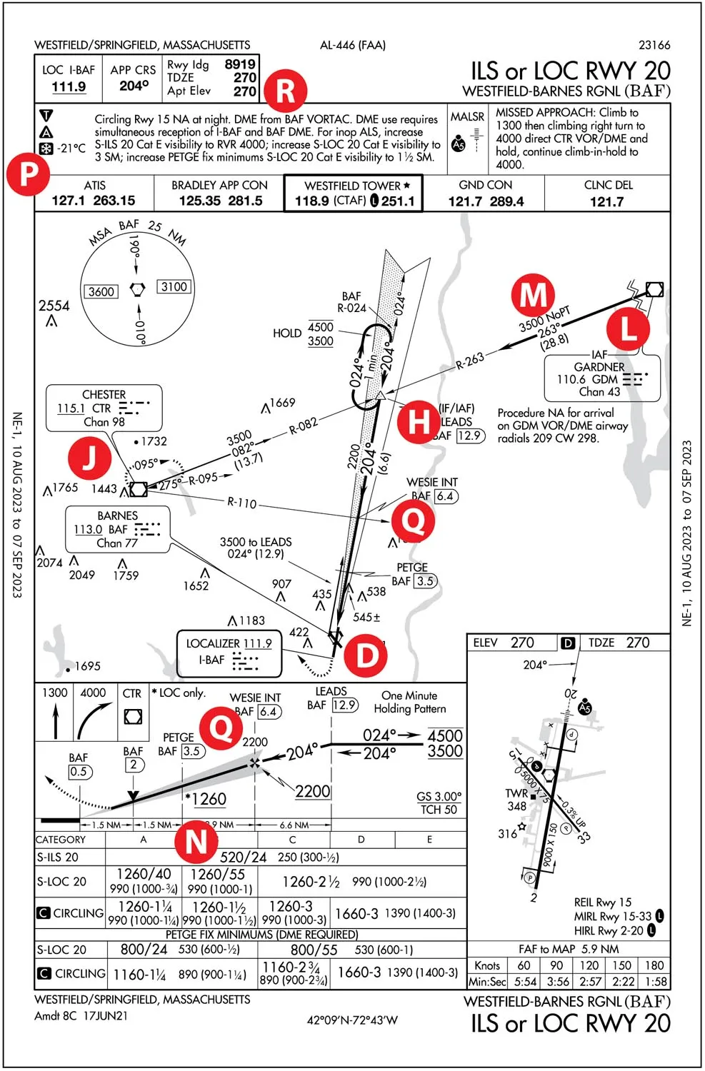 Compared to the military approach, the civilian approach is a typical ILS or LOC approach. It has two flyable routes, one from the GARDNER VORDME (GDM) L and the other one from the CHESTER VORDME (CTR). J However, using the CTR route, the angle of intercept of the LOC is at an acute angle, requiring an entry to the hold at LEADS H for the hold-in-lieu-of-procedure-turn (HILPT) course reversal.
But when using GDM as the flyable route, the route is annotated NoPT (no procedure turn). M However, given the traffic in the area due to Bradley International (KBDL) in Windsor Locks, Connecticut, to the south and Westover Air Reserve Base (KCEF) in Chicopee, Massachusetts, to the east, vectors from Bradley Approach Control are more likely.
In the minimums section, the ILS approach indicates that the DA for all aircraft categories (A through E) is 520 feet. It also indicates “/24” meaning a Runway Visual Range (RVR) of 2400 feet, which is equivalent to a 1/2 SM visibility. N This implies RWY 20 has RVR measuring equipment. Interestingly, the opposite runway (RWY 02) approaches do not show RVR values.
During low visibility, ATIS, METARS, and ATC typically report both prevailing visibility and an RVR value. In this case, the RVR value is controlling value only for the runway in question; for other runway ends, reported visibility is what controls. In METARS, RVR would be reported, for example, as R20/700V1200FT—Runway 20, RVR 700 feet variable 1200 feet when the visibility varies. Note that the required minimum RVR for the HI-ILS military approach is 50 (5000 feet) O compared to 2400 feet for the civilian ILS approach. N
DME distances along the final approach segment are based on BARNES VORTAC D, which is located inside the airport boundaries and appears to be co-located with the LOC. Not so. Unless we use GPS instead of DME, we need a NAV receiver for the LOC and a DME unit for the distances. However, in some DME installations, the DME is tuned through a ghost VHF NAV frequency using a VHF NAV head, implying that two VHF NAV receivers are needed—one for the LOC and the other one for tuning the DME using BAF.
Cold Temperature Airport
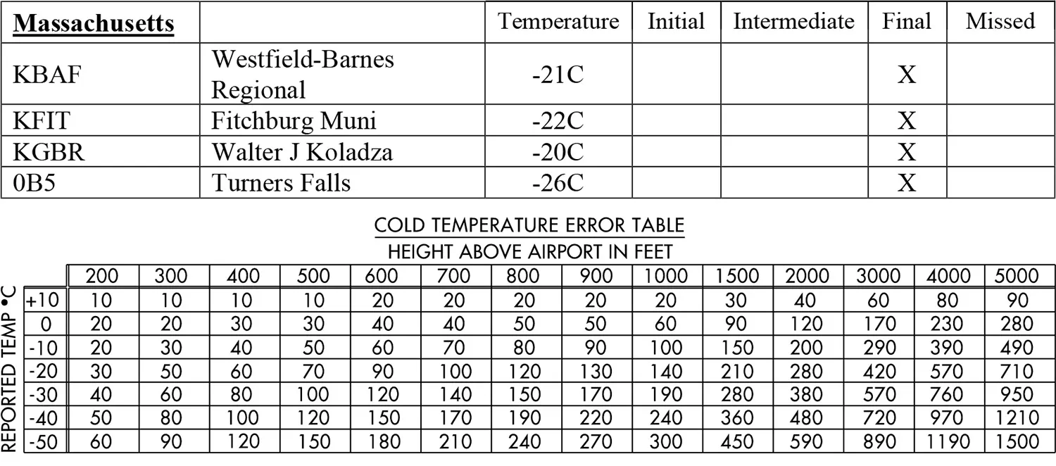
The snowflake symbol P indicates that Westfield is a cold-temperature airport (CTA). In Massachusetts, there are four CTAs. As expected, Alaska has the most, around 45, and Florida has none. The symbol also has a reference temperature of -21 degrees C or a cold -5.8 degrees F.
We are all familiar with the saying “from high to low, look out below,” referring to atmospheric pressure when the altimeter setting is not updated while flying to a low-pressure area. But the saying also applies to temperature. “From high to low temperatures, look out below,” especially during instrument approaches where aircraft are already low relative to the terrain and closer to obstructions. When the air is colder than standard, it results in denser air; the altimeter will erroneously indicate higher altitudes than the actual altitudes, possibly putting the aircraft dangerously close to terrain and obstacles. Whereas the low-temperature effect is less than the atmospheric pressure effect, we can ignore low cold temperatures during cruise flights but not during approaches.
Let’s suppose today Westfield is reporting -25 degrees C. Given the forecasted winds, we plan to fly the ILS RWY 20 using the GDM VOR as the IAF. Considering the temperature, altitude corrections are necessary for safety. We need to see what approach segments are affected by low temperatures. This information is in the FAA list of cold weather airports (https://aeronav.faa.gov/d-tpp/Cold_Temp_Airports.pdf). For Westfield, only the final approach segment is affected, specifically from the waypoint WESIE Q to the decision altitude (DA) on the glide slope. N
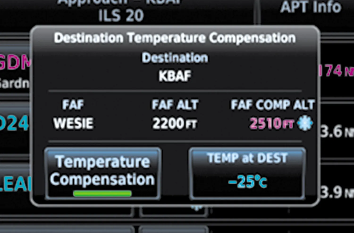 Some navigators, such as the Garmin GTN series, can calculate corrected altitudes, simplifying the exercise.The input is the temperature—in this case -25 degrees C.
WESIE now is 2510 feet MSL compared to the charted 2200 feet MSL. Note the snow flake next to the altitude. While not necessary since the initial and intermediate approach segments are not impacted, the GTN also provides a correction for those segments from GDM to WESIE. GDM and LEADS temperature-corrected altitudes are 4021 feet MSL instead of 3500 feet MSL.
The final altitude, whether a DA or MDA at a missed approach point, is left blank (RW20). The reason is simple: even though the GTN is a very capable navigator, it cannot read our minds! In other words which minimum altitude are we using? Let’s say we use the ILS precision DA of 520 feet MSL. N Other options for decision altitudes could be the LOC MDA or circling MDA. Also note that the GTN displays a temperature-corrected altitude at the holding fix (CTR). J (Not shown.)
For the manual DA calculation, use the Cold Temperature Error Table found in any U.S. Terminal Procedures Publication (TPP), page B1.
The steps are:
- Determine airport elevation, in this case 270 feet MSL R
- ocate the Decision Altitude on the approach chart—here 520 feet MSL N
- Subtract airport elevation from the DA. 250 feet AGL, which is also the HAT (Height Above Touchdown)
- Use the Error Table. Interpolate between -20 and -30 degrees C and between HATs of 200 and 300 feet. The correction is approximately 45 feet.
- Finally, add the correction (45 feet) to the DA of 520 feet MSL: 565 feet MSL, which becomes the new temperature-corrected DA.
 In case your navigator doesn’t offer cold-temperature corrected altitudes, a similar calculation logic would apply to WESIE. Performing the calculation manually, the result was 2530 feet MSL, which compares well with the GTN’s calculation of 2510 feet MSL and is well within the margin of error.
ATC should be informed when using temperature-corrected altitudes, for example: “Require 2510 feet for cold temperature operations at WESIE.” To ATC, it would appear that the aircraft is higher than it should be when, paradoxically, it is not.
Think Safety
When temperatures are very low, we should consider whether the flight is really necessary. Assuming the departure airport is also cold, engine preheat might be required, possibly even the cabin. Most importantly, are we properly equipped to spend time in cold temperatures if an off-airport landing is required?


