Aerodynamic wing stall accidents have been a concern since the canard was removed around 1910. Approximately 40 percent of General Aviation fatal accidents are due to loss of control with the majority of those being from stalls. One element of stall awareness training that’s not often taught is the details of sensors used to detect an aerodynamic wing stall and then how those sensors are used in a stall-warning system. Let’s fix that shortcoming.
Stalls
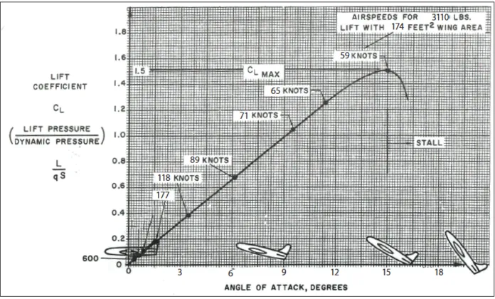
Stalls can happen at any airspeed, but only one angle of attack, the critical angle of attack. The airspeed changes with numerous variables including weight, load factor (bank/ G loading), center of gravity, air density, wing contamination (ice), etc. The wing’s angle of attack is the critical factor in determining how close the aircraft is to an aerodynamic stall. Therefore, an angle-of-attack (AoA) sensor is the ultimate stall warning and protection system.
Angle of Attack Sensors
Angle-of-attack sensors can be as simple as the lift detector switch tab or the Cessna reed. Both of these devices work on the principle that as the angle of attack changes, the stagnation point on the wing changes. The stagnation point is where the wind separates into the flow above the wing and the flow below the wing. As the angle of attack is increased the stagnation point moves aft.
It’s easiest to visualize the lift detector switch tab. In cruise flight, the tab is pushed back/down by the relative wind going under the wing. As the angle of attack increases the stagnation point moves aft (or down) and as the angle of attack is increased further, the stagnation point moves behind the tab. With the stagnation point behind the tab, the airflow will push the tab forward/up. When the tab is forward, a microswitch closes and the stall warning is activated.
Leonard Greene invented the lift detector in the 1940s and modernized versions are still used today. Instead of simply detecting if the tab is forward or back a lift transducer incorporates a sensor to determine the force on the tab and its position. This provides a measurement of the angle of attack around the critical angle of attack (CL-Max).
The movement of the stagnation point is greatest near the stall. This makes a lift detector or lift transducer accurate and repeatable. Of course, the positioning of the lift detector or transducer on the wing is critical. If the lift transducer is part of the certified stallwarning system, the positioning is determined during flight test.
AoA Vanes
Larger aircraft typically use an angle-ofattackvane on the fuselage. An angleof-attack vane is basically a weathervane. The AoA vane protrudes into theairstream to align with the local airflow.While basically a weather vane, the internaldesign is much more complicated.The external vane is counterbalancedto improve low-speed sensitivity and isdamped to eliminate any jitter or flutter.The external vane itself is heated for usein icing conditions.
Airflow studies using computer aided design tools are used to determine the best position for mounting the AoA vane on the aircraft. After mounting, flight testing will be done to determine the local angle of attack that produces CLA-Max. The actual free airstream differs from the local airstream due to the effect of the fuselage/radome and wing faring. Depending on the aircraft, the free airstream airflow will start to be affected by the airframe several feet in front of the aircraft. However, the AoAmeasured by the vane is the local AoA. The local AoA on the nose of the aircraft is typically two times more sensitive than the free airstream AoA. The vane angle at the stall is recorded for each flap position while the aircraft is in flight-test status.
AoA from Differential Pressure
The SmartProbe from UTC Aerospace uses differential pressure to determine the angle of attack. AoA ports are added to a pitot/static probe to become an integrated air data probe. In cruise flight the pressure on the top of the tube will be close to the pressure on the bottom of the tube. Small ports (holes) are made in the tube to route the air pressure back to a computer to measure the pressure difference and calculate the angle of attack. As the angle of attack is increased, the underside of the tube will have a higher pressure than the top. Again, through flight testing CL-Max will be determined and the differential pressure at the stall will be measured.
Lower-cost differential-pressure angle-of-attack systems are available from Alpha Systems, Garmin, and others.
Calculated AoA
It’s possible to calculate AoA based on inertial data. Aspen Avionics uses such a derived AoA. Adding AoA to Aspen’s Evolution display does not require any additional sensors. In November 2017 the FAA published a paper titled “Flight Test Results of Direct Measure and Derived Angle-of-Attack Systems for General Aviation Airplanes.” The paper features Garmin’s “sensed AoA” and Aspen’s “derived AoA.”
Stall-Warning System
Because of the unique characteristics of angle of attack, all “artificial” stallwarning systems will utilize AoA as the primary input. The stall-warning system for a light aircraft can be as simple as we’ve discussed. Some Part 23 business jets have a single AoA sensor vane, where more sophisticated stall-warning systems will utilize two independent stall warning computers and two AoA sensor vanes.
Stall-protection systems carry the stall-warning system to another level. Stall-protection systems use a pusher to force the yoke forward to prevent a stall. They came about early in the jet era. Most of the swept-wing air transport aircraft of that era had poor stall recovery characteristics. Because of that, the FAA required a system to prevent a stall from happening in the first place.
Most “pusher systems” are still in Part 25 Air Transport aircraft, but there a few in Part 23 aircraft. If the aircraft designer and the regulatory authorities feel the stall characteristics are marginal then a stick pusher will be installed. Preventing a deep stall situation where the wing blanks out the elevator in a T-tail aircraft would be a more serious case requiring a pusher.
The force for the push used to come from a separate servo motor. However today, more manufacturers are using the autopilot pitch servo to accomplish the push. When the AoA reaches a predetermined value the push will occur.
It’s called a pusher but in the implementation, it’s actually a pull. Either an independent motor or the autopilot servo will pull on a cable to move the yoke forward. If CL-Max is normalized to 1.0, the stick pusher will typically fire around 0.97 and remain in a push state until the system senses that the stall-warning trip point has been passed. The actual “firing point” will be determined during flight test.
A pusher system requires a higher level of safety to prevent an accidental push. You can understand the consequences of an inadvertent push in cruise flight. A stall-protection system will normally utilize at least two independent computers with two or more independent AoA sensors. Both computers must have issued stall warnings and both have to agree to push. Typically, the pilot would be required to test the operation before every flight. It is better to have a stall protection system that fails safe—no push— than one that pushes inadvertently.
Stall-warning systems beyond the most basic will include flap position (CL-Max, the critical AoA, changes with flap position) and an input to adjust the warning for ice accretion. This can be from an ice detector or the anti-ice system being turned on. Landing gear position is incorporated in some systems and Mach compensation is used in most jet stall-warning systems. Weight on wheels logic is usually used to disable the stall-warning system on the ground.
How are dual stall-warning systems better than a single system? First, there is redundancy. One side can fail and you still have stall warning on the opposite side. If either system calculates that a stall is imminent then that side will issue the warning. In a yaw, one system will indicate a higher angle of attack than the other. The higher AoA wins and a stall warning is issued.
Traditionally in air transport aircraft, the stall warning is done with a stick shaker. This device vibrates or shakes the yoke to simulate the feeling of a stall buffet. It is very noisy and the combination of the shaking and noise usually wakes up any pilot. Light aircraft use a stall warning horn while some of the later systems have a voice call out of “Stall”. Early Piper Cherokees had a red annunciator light to indicate a stall, but that is no longer deemed adequate for new aircraft certifications.
AoA indicators can range from glare-shield mounted bar graph displays to three light fast/slow displays, to analog round-dial instruments. A normalized AoA indicator will typically be calibrated to 1.0 at CL-Max or stall, and 0.0 as zero lift. Approach speed is typically 1.3 VS which equates to a normalized AoA of 0.6.
Turbine aircraft operators calculate their VREF speed based on the aircraft weight. Knowledgeable pilots will cross check the AoA on approach to assure that an incorrect weight was not used in the calculation. (It happens.) Light aircraft operators can use glare-shield mounted bar graph displays to aid them in maintaining the proper approach speed while keeping one’s eyes outside. Adjusting the pitch and then trimming to hold the center donut or reference point will lead to more consistent stabilized approaches and better landings.
What Do You Fly?
We’ve covered the basics of a stall-warning system, but you should dig into the details of the system on your aircraft.
• Is a preflight check required?
• Is it usable in icing conditions? If so, is there an “advancement” of the stall warning to account for aerodynamic changes with ice? (Many older stall-warning systems were certified before this requirement.)
• If it is a later system, what activates the advancement of the stall warning for icing conditions?
This is Important
You might routinely dismiss the stall warning system as insignificant. However, being a simple and reliable system doesn’t make it insignificant. There was a fatal Phenom 100 stall accident on December 8, 2014, in Gaithersburg Maryland that illustrates this point.
The Embraer Phenom 100 stall warning and protection system has an “ice schedule” that adjusts parameters when deicing equipment is turned on. From the NTSB’s report: CVDR data show that, before beginning the descent, the pilot set the landing reference speed (VREF) at 92 knots, indicating that he used performance data for operation with the wing and horizontal stabilizer deice system turned off and an airplane landing weight less than the airplane’s actual weight. Using the appropriate Normal Icing Conditions checklist and accurate airplane weight, the pilot should have flown the approach at 126 knots (a VREF of 121 knots +5 knots) to account for the icing conditions.
The NTSB found that the pilot’s failure to use the deice system during the approach led to ice accumulation, an aerodynamic stall at a higher airspeed than would occur without ice accumulation, and the occurrence of the stall before the aural stall warning sounded or the stick pusher activated. Because the deice system was not activated by the pilot, the band indications (low-speed awareness) on the airspeed display did not appropriately indicate the stall-warning speed. The NTSB’s aircraft performance study found that there would have been sufficient warning of a stall had the device system been used during the approach. Once the airplane stalled, its altitude was too low to recover.


So, what AOA is recommended for a small plane?
Jim, thanks for the question. There are two basic ways that AoA can be determined. The first is through a sensor hence the term “Sensed AoA.” The second is to use inertial data to calculate the aircraft AoA. This is called “Derived AoA”
There are also various ways to sense the angle of attack. Each measurement technique has advantages and disadvantages. One disadvantage of all sensed AoA systems is finding a suitable mounting location on the aircraft. The location needs to be structurally sound and have proper airflow to accurately sense the change in the relative wind. Aircraft manufacturers use computational fluid dynamics programs to select the proper mounting location.
One technique is to measure AoA is from a wing-mounted tab. The tab is connected to electronics to measure the force on the tab from the relative wind. They are mounted so that the stagnation point is behind the tab near the stall, pushing it forward. Safe Flight Instrument Corp. is the primary manufacturer of these lift transducer products. The disadvantage of this type of sensor is that you must cut a hole in the wing’s leading edge to mount the transducer. Also, Safe Flight’s SCc® is approved for mounting on the right-wing of aircraft only if a Lift Detector or Lift Transducer is mounted on the left-wing. The reasoning is that the installation of the lift detector didn’t compromise the left wing’s structural integrity, then mounting the SCc’s detector on the right-wing in the same fashion will not compromise the right wing’s integrity. Hence it is considered a minor modification. The disadvantage becomes an advantage in that both wings now are measuring the airflow/stagnation point change. Another advantage is the “tab” is less susceptible to sideslip affecting the measurement. [Full disclosure: I retired from Safe Flight in 2017]
Another popular method is differential pressure sensors which use two ports to sense the pressure difference. They are mounted such that as the AOA increases, the differential pressure between the two ports decreases. Alpha Systems, Garmin, and Levil Aviation are major suppliers of this type of AOA for light aircraft. The advantage is they are easier to mount but a disadvantage is that they are more susceptible to sideslip (spanwise flow) affecting the AoA measurement. (The disadvantage is debated among manufactures.) Several Air Transport aircraft and some business jets use differential pressure sensing for AoA utilizing UTC Aerospace’s SmartProbe®.” The issue of sideslip is minimized by having multiple SmartProbes on the aircraft.
A third offering is an aircraft-mounted vane. These are also found on Air Transport Aircraft. For light aircraft, these are a wing or strut-mounted vane (small torpedo shape tube with a rear fin.) The advantages are reduced susceptibility to sideslip and ease of mounting. CYA makes this type of AoA sensor.
Lastly, there are derived/calculated AOA based on inertial data. Aspen and uAvionix calculate AOA using inertial sensors. On the disadvantage side, the derived AOA is only as good as the sensor set. The higher the quality of the inertial sensors, the better the derived AoA. As the quality (and price) of the basic sensors drops, so does the accuracy. Lower cost MEMS sensors often have issues with cross-axis interference and vibration. Lastly, Air Transport aircraft have excellent gyros and accelerometers to calculate the flight path angle (relative wind); however, Boeing and Airbus still rely on “sensed AOA” rather than derived AOA. Having said that, “Derived AOA” has a considerable advantage of not requiring any external mounting or no additional hardware in the case of Aspen.
So, hopefully, that provides some background for you to select the best AoA Sensor for your light aircraft.