After deciding I wanted as much redundancy—immunity from any single failure—as possible, and designing the systems toward that goal (See “Belt, Suspenders, Rope” in September 2023.), it only remained to actually install and implement those systems. That required about three and a half months and cost about half what the plane had been worth.
Where? Why?
When I acquired this 1982 Cessna 340A, I lived on the Central Coast of California. The best avionics shop to help me maintain that largely original bird was Executive Autopilots at Sacramento Executive Airport. They were experts in the older analog electronics then in the aircraft.
Thus, it made sense to stick with them for the first major upgrade to include EFIS and a GTN navigator. Later I moved to Santa Fe, New Mexico. I sought a closer alternative, but didn’t find one that made me as comfortable as Executive Autopilots. So, based on that comfort and their familiarity with my plane, I stuck with them to install Garmin’s GFC 600 autopilot, and later, this next complete makeover.
What?
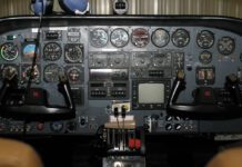
This upgrade featured dual GTN Xi navigators and a dual G500 TXi EFIS with engine information systems (EIS) displaying on two 10.6-inch displays. The EIS presents many options and alternatives (more later). I replaced all the engine instrumentation, from the manifold pressure and tach to fuel gauges and even the vacuum gauge.
Previously I had a Garmin G5 as the standby, but I chose to redeploy the then-right-side Aspen Evolution (upgraded to Max) as the standby. For reasons I can explain but not fully justify, I retained my King KN 63 DME and the KR 87 ADF. Like everything else, they indicated on the TXi displays.
Rounding out the panel, I kept my GFC 600 autopilot and the GTX 345 ADS-B (In and Out) transponder, plus a uAvionix AV-20 multi-function instrument with its convenient clocks and timers. Behind the scenes I also had Garmin’s GWX 68 radar, a legacy GDL 69 Sirius XM receiver, GTS 820 active traffic system, and a Stormscope, all displaying on the TXi. (However, one reason for the GTN 750 Xi all-in-one navigator was its large display that I operationally dedicate to show traffic.)
Building It
One big challenge was how Cessna decided to build and mount the instrument panel. The OEM panel was three separate panel pieces that overlapped for mounting, with the radio panel behind the left and right instrument panels. I’d improved that in the first upgrade years ago by using a product called RadioRax for panel support and avionics mounting, and designing the separate panel pieces so they dovetailed together instead of overlapping—any one piece could be removed without disturbing the other two.
However, as I’d built it previously, the right panel wasn’t wide enough to accommodate the 10.6-inch TXi display. So, the shop did some refitting to enlarge that panel and take now-excess width from the left side. They did a superb job and the new panel is smooth and contiguous, looking as if it’s OEM.
Fuel Measurement
Two types of fuel-level measurement systems are in common aviation use today. One is the familiar float-type with a float on an arm that pivots as the amount of fuel in the tank changes. At the pivot, there’s generally a variable resistor whose value depends on the position of the float. These systems are simple and inexpensive, but often unreliable as they age, no longer reading correctly or smoothly.
The other type, which is more common in larger and transport category aircraft, is a capacitive sensor. There are no moving parts. Instead, there is a probe arrangement with two electrodes (low voltage, low current) that extends the depth of the tank. The amount of fuel changes the capacitance between the electrodes, which is measured as volume of fuel. This is generally considered to be a superior system.
In this aircraft, Cessna used the capacitance system. However, their implementation was somewhat flawed in my opinion. With such low-level signal characteristics, ideally the circuit that measures the capacitance and converts it to a signal usable for fuel gauges should be as close to the capacitance probes as possible. Presumably as a cost-savings measure, Cessna used just one per wing, switched to read between the tip and wing tanks, located adjacent and outboard of the engine.
This “signal conditioner” has all the probes wired to it along with switch inputs that tell it which tank the pilot is interested in seeing. Over time, the long wiring from the probes to the signal conditioner deteriorates a bit. This is enough to affect the very sensitive capacitance level sensed at the probes, and can dramatically affect the accuracy of the reading.
CiES is a company that makes replacement float-type sensors that utilize a digital method of level sensing and transmission of the signal. They’ve achieved a good reputation for quality products, and they make replacement fuel-level sensors for the Cessna 340 that I wanted to try. I had my local mechanic install these sensors before going to the avionics shop.
The OEM system had one gauge for each wing that was switched between reading the tip tank and the wing tank by the fuel selector position to read only the tank in use, but also with a momentary override toggle switch so the pilot could read the other tank. This worked well for what it was, subject to the aging wiring issue. Nonetheless, it was confusing to those who weren’t trained on it and has resulted in some accidents.
 Garmin’s EIS has the ability to display all four tanks at the same time. It could do so using the OEM capacitive system, but the tank not currently selected shows the last known level and is grayed out. By replacing the OEM capacitive system with the CiES digital sensors, all four tanks actively read all the time, which is more desirable and less confusing.
CiES installation instructions and materials were inadequate, saying little more than, “mount the sensors in the tanks.” (—an exaggeration to make a point) And, since the sensor had to be mounted entirely inside the tip tanks, the wires needed to penetrate the tank. No provisions or instructions were provided for this, leaving wiring specifics and many of the other details of the installation up to the installing shop to engineer, including selection of the bulkhead connector for the wiring. The installation of the CiES sensors in my airplane required well over 100 hours of labor and later resulted in a failure of a seal, dumping more than 20 gallons of avgas on my hangar floor.
While I’m now happy with the final result, I believe the installation of the CiES sensors was far more challenging than any STC-approved product should be. I’d recommend CiES more thoroughly engineer this installation, and provide more explicit instructions and a complete package of materials.
Final Configuration
I mentioned earlier that the EIS provides nearly endless options for configuration of the engine-instrument displays. With the 10.6-inch GDU 1060 display, there is one always-on strip of gauges that displays the most important data, then a page on the MFD to display more information. Exactly what information is displayed, however, is selectable only by the shop for the strip, and by the shop and the pilot for the MFD page. This led to a number of false starts as we sought the ideal configuration.
My strong recommendation for any owner and any shop installing an EIS is for the shop and owner to work cooperatively to determine exactly what is to be configured and how. For example, the EIS strip can display CHT, but it only displays the hottest CHT for each engine. This is a practical solution to the limited space on the strip. But, one would think that the same logic used for displaying CHT would also be used to display EGT. It isn’t.
Instead, the EIS strip can only display a single dedicated EGT probe, which can’t be part of a multi-probe EGT installation. The reasoning here has to do with a common OEM installation of only one EGT probe and certification issues. Of course, the strip can display TIT if you’d prefer. I lean watching individual CHT and EGT probes on each cylinder. This isn’t possible today for EGT in the EIS strip, instead forcing me to the MFD display to show the full EIS information page where you can, indeed, see each cylinder EGT. To me, this is a limitation that should be addressed.
How?
I’ve currently only got about 15 hours flying the TXi with EIS and the GTN Xi navigators. I’ve been able to fumble my way through, but I certainly haven’t learned how to expertly use everything. That’s my next undertaking and I’ll report on that shortly in the final article in this brief series.


